
FAQ
NOTE 1.1 Explanation of LED fundamentals
LED is a light emitting semiconductor device with diode-like characteristics. As forward current flows through the P-N junction of the semiconductor material, photons are released as a result of electrons moving across the diode and falling into the empty holes in the P-type layer. Depending on the photon’s frequency, it could either be invisible to the human eye (infrared portion) or be part of the visible spectrum. The lasted development in LED technology involves coating blue LED with phosphor to create white LED.
The V-I curve of LEDs is similar to diodes. Please refer to figure 1.1
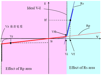
Figure 1.1: LED V versus I characteristic
White LEDs are generally used for lighting applications, the brightness of such device increases proportionally with the increase in forward conduction current. Due to the rise in demand for high power, high luminance white LED in the lighting industry, specifications are being standardized. Forward voltage is typically within the range of 3.0~3.5V with forward current of 350/700/1050mA resulting in power rating of 1/2/3W.
NOTE 2.7 Adjustment of output voltage and current
Some MEAN WELL’s LED power supplies equip with functions of adjustable output voltage and current. Models with IP67 design (potted with heat transfer silicone) do not allow adjustment of output voltage and current, but HLG-150A/240A is with special design that allows external adjustment; for models with plastic enclosure, adjustment can only be made after taking apart the top cover. Adjustable voltage range will be +/-10% or +0/-15% of rated value and adjustable current range will be about 50~100% of rated value.
NOTE 2.9 Suggested solutions for EMC of LED luminaries
- Metal enclosure grounded to FG (Frame Ground):
- For applications with FG connection, it is suggested to bond the metal cases of LED power supply and LED module to FG to reduce EMI (Electromagnetic Interference) of the whole system.
- Wiring:
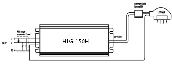
- Since the input and output cable length can be meters due to actual field applications, the common mode noise can be highly significant. To effectively reduce the noise, a clip-on common-mode core can be installed on the wiring close to LED module. This solution also applies if AC input cable is too long. Please refer to Fig.2.9 for illustration.
- High surge level requirement:
- In order to meet requirement of surge level for outdoor applications, the surge immunity of HLG-60/100/150/240 is designed to be up to 4KV. For surge immunity of higher level, varistors or gas tubes (500V rating) can be installed in the outside of the power supply. But the configuration should also comply with requirements in safety norms. Please refer to Fig.2.9 for illustration.
- LED module with driver IC:
- Since LED driver IC is a circuit topology employing high frequency switching (hundreds of KHz to several MHz), using it to deliver constant current to LED modules can complicate EMI debugging. Due to the EMI concerns, it is more than important to suppress the noise from driver IC. The PCB layout should focus on the size of driver IC’s ground trace and configuration of In/out capacitors and inductors. It is suggested that common choke, differential choke and high-frequency X capacitor should be incorporated into the PCB layout between the output side of power supply and the circuit of LED driver IC. Please refer to Fig.2.10 for illustration.
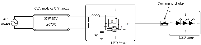
Fig.2.10 Illustration of suggested EMI solutions for LED driver IC
NOTE 1.2 LED applications
Advantages of LEDs include low heat dissipation, diverse applications, miniaturization, high tolerance to shock/vibration, and ability to focus light beam. The use of white LED in the lighting industry is accelerated by the continuing improvement in luminous flux and efficiency. Typical applications include building architecture (wall lighting, wall decoration, garden lighting, spot lighting, stairway lighting, and patio lighting), outdoor use (street light, park light, and lamp post), commercial use (office lighting, sign board, display cabinet lighting), and home use (cabinet lighting, room lamination, desk lamp, and etc).
Why the input voltage marked on the spec. sheet is 88~264 VAC while the label on the power supply says that it is 100~240VAC?
During safety verification process, the agency will use a stricter standard -- ?0%(IEC60950 uses +6%, -10%) of the input voltage range labeled on the power supply to conduct the test. So, operating at the wider input voltage range as specified on the spec. sheet should be fine. The narrower range of input voltage labeled on the power supply is to fulfill the test standard of safety regulation and make sure that users insert input voltage correctly.
Will MEAN WELL's products with CE marking meet the EMC requirements after assembling into my system?
We cannot guarantee 100% that the final system can still meet the EMC requirements. The location, wiring and grounding of the switching power supply in the system may influence its EMC characteristics. In different environment or applications, the same switching power supply may have different outcomes. Our test results are based on setup shown in the EMC report.
NOTE 1.3 LED lifetime and reliability
Since LED is part of the solid-state semiconductor device family, when properly designed-in, it has excellent lifetime and reliability figures. The lifetime of LED is typically between the range of 50,000~100,000 hrs. This exceeds the lifetime of the traditional lighting device (1,000~10,000 hrs) by a large margin. Extra attention must be given to cooling of LED and design of LED driver or else you risk premature failure and accelerated the decrease in luminance (refer to figure 1.2). The key to achieving energy conservation, high efficiency, and long lifetime is to select a suitable power source/drive method and provide proper cooling for the LEDs.
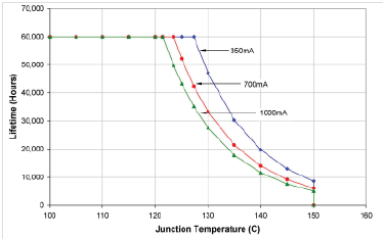
Figure 1.2: LED junction temperature versus lifetime
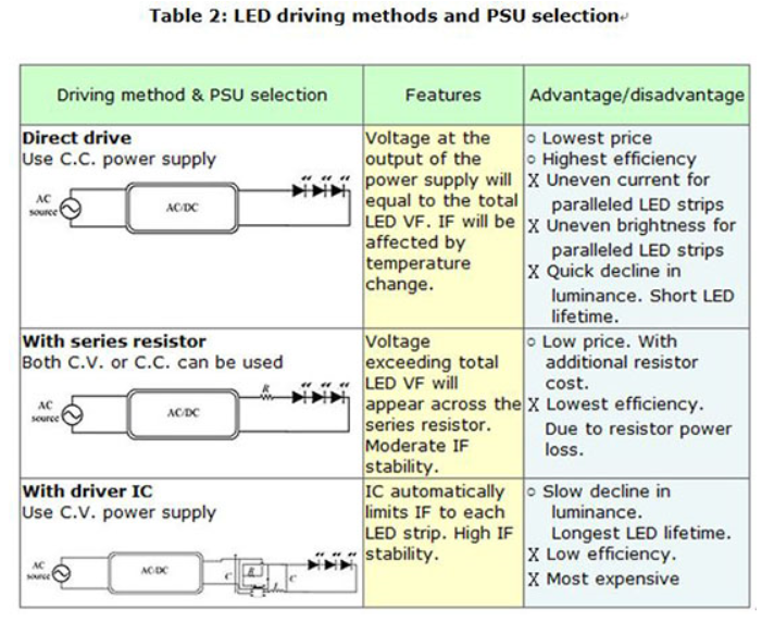
NOTE 1.4 LED drive methods
The main factor to driving a LED is the introduction of forward current. However, due to its nonlinear V-I characteristic, high Vf manufacturing tolerance, and Vf sensitivity to temperature change, the most common types of voltage source used are limited to either constant voltage or constant current. The drawback of using constant voltage source is that LEDs will not produce the same brightness, resulting in uneven reliability, decrease in luminance and lifetime. For these reasons, the constant current voltage source is more preferable when it comes to driving high power LEDs. Just as named, the constant current source is not susceptible to the variations in forward voltage. Its current will remain at a constant level regardless of the shift in LED Vf. Thus, constant brightness can be easily achieved. Constant current can also be attained by using a driver circuit with current sense resistive network so no adjustment of the power supply voltage is required.
What is different between information (EN60950-1) and medical (EN60601-1) safety standard?
According to safety standard, the leakage current in EN60950-1 Class I cannot exceed 3.5mA; in EN60601-1 cannot exceed 0.3mA. Others criteria like safe distance and numbers of fuse are also different. Please consult the diagram below:

What is class 2, class II and LPS? What is the difference between class I and class II?
Class I: Equipment where protection against electric shock is achieved by using basic insulation and also providing a means of connecting to the protective earth conductor in the building where by routing those conductive parts that are otherwise capable of assuming hazardous voltages to earth ground if the basic insulation fails. This means a class I SPS will provide a terminal/pin for earth ground connection.
Class II: Equipment in which protection against electric shock does not rely on basic insulation only, but in which additional safety precautions, such as double insulation or reinforced insulation are provided, there being no reliance on either protective earth or installation conditions. This means a class II SPS does NOT have a terminal/pin for earth ground connection.
LPS: When an electronic circuit is powered by a limit power source (LPS), its output current and power are under the limitation shown in IEC60950-1 Table 2B, and the risk of fire can be reduced significantly. So, the safety distances and flammability rating of components can be much lower. Therefore, the plastic enclosure of these power supplies could use HB flammability rating to reduce cost. This definition comes from ITE product (IEC/EN/UL60950-1).

Class 2: When an electronic circuit is powered by class 2, its output current and power are under the limitation shown in UL1310 Table 30.1, and the risk of fire can be reduced significantly. So, the safety distances and flammability rating of components can be much lower. Therefore, the plastic enclosure of these power supplies could use HB flammability rating to reduce cost. This definition comes from UL class 2 power unit (UL1310).

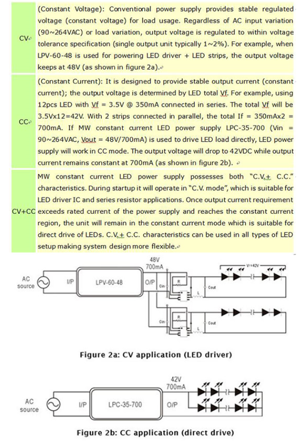
NOTE 1.5 Introduction to Constant Voltage (C.V.) Mode and Constant Current (C.C.) Mode of LED Power Supply
Most of the traditional switching power supplies provide a constant voltage (C.V.) to the load. For example, MEAN WELL’s single output model RS-25-5 can provide 5V/0~5A to power all kinds of load. Its output voltage maintains at the constant value of 5V while its output current varies from 0~5A based on the load condition. When the loading is over 5A which is its rated current, the power supply unit will go into “overload protection” mode (generally speaking the activated range of overload protection is 105%~150% of rated output power). There are many different protection types that are often seen in the design of MEAN WELL power supply such as shutdown type (PSU will be shut off output), hiccup type (output voltage/current will be pulsing), and constant current type (output current will be fixed at a constant value between 105~150% of rated output current and the output voltage will go down to a low level). The power supply is under abnormal condition when the overload protection has been activated, so it is not suitable to let the power supply unit operate under this situation continuously. Equipped with “hiccup type” as their overload protection mode, the LPV, LPH-18 and LPL-18 series in MEAN WELL LED power supply family are considered to be “constant voltage power supply”. For LED related applications, it can be used in system incorporated with LED constant current driver IC (Fig. 1.5) or series connected with a ballast resistor (Fig. 1.4).

The so-called constant current (C.C.) LED power supply basically refers to the “constant current protection” concept and its output current is maintained at a fixed value by means of feedback control (this fixed current level will be close to its rated output current). The only difference is : Under constant current (C.C.) operation mode (or constant current protection mode), the C.C. LED power supply is still within the normal operating range and all the components have been chosen to continuously provide this constant current output. Generally speaking, the power supply unit will operate under constant current region only when the system design belongs to “LEDs drive by the power supply directly” (Fig. 1.3).
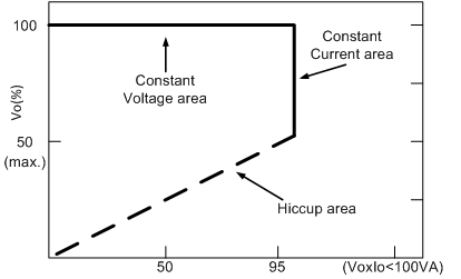
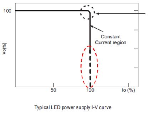
Figure 1.6: Typical LED power supply I-V curve
Fig. 1.6 is the I-V characteristic curve of a typical constant current LED power supply. The “constant current region” for each series of C.C. LED power supply may be different because of the different circuit design. As the figure shown above, the PSU will operate in the constant current region only when the output voltage is kept at 50% of rated output voltage or higher, so the sum of VF of all series connected LEDs should be higher than this limitation. If the sum of VF of all series connected LEDs can’t achieve 50% of rated output voltage, the power supply will go into the “hiccup region” and cannot drive the LEDs properly. Currently most of MEAN WELL’s LED power supplies can provide constant current output and the suitable operation region for directly connected LEDs is also specified in their SPECs (in the column of “Constant current range”). The constant current region can be 3V~100%VO, 9V~100%VO, or 70%~100%VO in different product series because of the difference of circuit design (concerning Harmonic Class C compliance, the lower limit may reach 75% of rated output voltage for some models with PFC function). When using power supply to drive LEDs directly, designer of lighting fixture should make sure that the VF sum of LEDs connected in series is high enough to operate the C.C. LED PSU in the correct region.
In fact, MEAN WELL’s constant current LED power supplies also possess the feature of “C.V. + C.C.”. That means before reaching the “constant current region”, they can be operated within the “constant voltage region” just like traditional power supplies. In this region, system design must incorporate suitable “LED drive IC” or “series connected with a ballast resistor”; after entering the “constant current region”, the PSU can provide constant current as the output and hence can drive the LEDs directly. We can find that the “C.V. + C.C.” characteristic can be used in many different LED installations and make the system design more flexible.
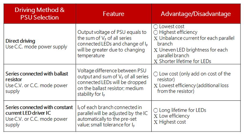
Below is the comparison chart of three different LED driving alternatives:
NOTE 1.6 LED lamp driver structure
The most often seen LED lamp setup is the series configuration because this ensures equal brightness to each of the LEDs. Even if the lamp consists of the same LED components from the same production lot there will still be slight differences in the forward voltage. As the working temperature increases, the LED forward voltage is bound to decrease leading to an increase in the forward current. This is why it will be necessary to add the current limiting circuit to the LED setup. The most common driving structures are as below:
- LED directly driven by a power supply Figure 1.7
- This setup is the most cost-effective and wirings are simple. The designer will only have to worry about LED characteristics. Once that is taken care off, all the designer has to do is select a stable power supply with constant current limiting. However, there could still be issues with equal current sharing between each of the LED strings. Matrix LED structure can be used to minimize extensive damage from the
failure of just a few LED. If a MEAN WELL constant current LED power supply is used to drive LEDs, the direct connection is possible and current limiting resistors and LED driver ICs are not required to somewhat balance the current flow to each LED string. However, the LED must be ranked in order to minimize large differences in Figure 1.7 combined VF of each of the LED strings which can lead to unbalance current flow to some of the strings and cause part of the LED structure to be damaged from the high current flow.
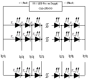
Figure 1.7 Constant current power supply drive LED load directly
- Series connection of LED current limiting resistor, refer to Figure 1.8 Series
- The advantage of this architecture is that it is inexpensive and rather easy to assemble. Better balance in output current as compared to the direct drive method. The disadvantages are high power dissipation of these resistors, If current varies with the change in voltage, LED brightness may be uneven, cannot control current precisely and lack of protection for the LEDs.
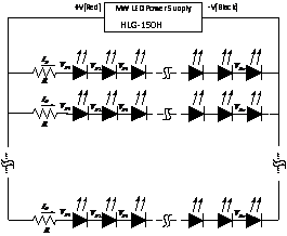
Figure 1.8: Constant current or constant voltage power supply with LED driver resistor
Example:
The use of CLG-150-30(30V/5A) to drive 8 LEDs in series and 8 strings in parallel
V : LED power supply rated output voltage
VF : LED forward voltage (around 3.5V)
IF: : LED forward current (about 625mA)

-
-
- Power supply in combination with linear driver IC, see figure 1.9
The cost of this structure is moderate. Other advantages include long lifetime for both LED and the power supply, simplicity of circuit design. Disadvantages includes higher cost as compared to using driver resistor with just as much power dissipation, and unsuitable for use with high tolerance voltage source.
Linear constant current driver can not automatically adjust the current flow to the LED. It does not balance current as well as PWM constant current driver. Its basic IC structure composes of resistor + electronic switch. LED drive current is regulated through the control of the switch’s conduction level.
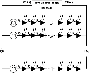
Figure 1.9: Constant current or constant voltage power supply with linear LED driver-
- Power supply in combination with PWM constant current driver IC, see figure 1.10
The PWM constant current driver will automatically adjust current flow to achieve balance in current for each LED string thus insure each branch has equal brightness. Main topologies include buck, boost, and buck-boost. Either pulse width or frequency is modulated to maintain constant current.

Figure 1.10: Constant current or constant voltage power supply with PWM constant current LED driver -
What is SELV for information products?
This regulation applies to the secondary circuitry. The circuit should be designed to guarantee that under normal operating conditions, the voltage between any two touchable points should be less than 42.4Vpeak or 60Vdc. For class I equipment, it refers to "between any touchable point and the ground." Under single fault conditions, the voltages between any two conductors of the SELV circuit and between any one such conductor and earth shall not exceed 42.4V peak or 60Vdc for a period longer than 0.2 seconds. Moreover, a limit of 71V peak or 120Vdc shall not be exceeded. According to requirements below, MW SPSs can comply with SELV. IEC 60950-1 (ITE SPS): voltage of o/p circuit is less than 60Vdc under normal condition. IEC 61347-2-13 (LED SPS): voltage of o/p circuit is less than 120Vdc under normal condition.
What is LPS ? If the power supplies can meet LPS, what is the benefit for the end product?
The requirement of LPS is from IEC60950. It means the product output shall not exceed 60V/8A/100W under the normal and abnormal condition.
If the power supplies can meet LPS , the end product does not need the fire enclosure.
NOTE 2.1 Instructions on Assembly
- As step 1 shown in figure 2.1, connect LED luminaries to the output cable of Mean Well LED power supply.
- As step 2 shown in figure 2.1, connect the input cable of Mean Well LED power supply to AC mains.
- ! CAUTIONS: Step 1 should always come before step 2. If step 2 comes first, a high transient surge current will go into the LED luminaries and it can damage LEDs in an LED luminaries without LED driver IC.
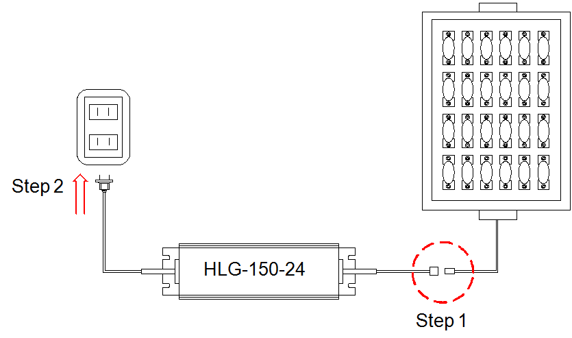
Fig.2.1: Assembly of LED power supply
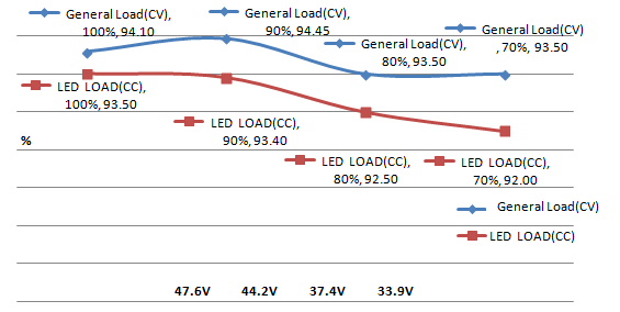
NOTE 2.3 Effect of output load on efficiency
The types and levels of output load have significant effects on the efficiency of a power supply when operating at normal conditions. The chart below presents the change of the efficiency of HLG-150-36 operating at 70~100% LED load and 70~100% general load, and indicates that the efficiency will be lower as the total Vf (forward voltage) of LEDs in series is lower when LEDs are directly powered by LED power supply. Therefore, it is a better design to set the total Vf of LEDs in series at 85~95% of the rated voltage of the power supply.
What is LVLE ? If the power supplies can meet LVLE, what is the benefit for the end product?
According from UL8750 definition below:
a. 0-30Vdc output voltage: Maximum 8 amps
b. 30-60Vdc output voltage: 150/V amps
If the power supplies can meet LVLE , the end product does not need the fire enclosure.
What is MOOP and MOPP?
a. MOOP: provide adequate protection to the operator
b. MOPP: provide adequate protection to the patient
c. MOP: only one protection
MW products declare 2 MOPP means that MW product can provide two adequate protections to the patient.
It minimum the risk and also suitable for the patient.
NOTE 2.2 Protection function
All of MEAN WELL’s LED power supplies are designed with protection functions against inrush input current, peak input voltage, short-circuit at output, overload (OLP) at output and over voltage (OVP) at output. Some models also equipped with over temperature protection (OTP). Please refer to Mean Well’s switching power supply technical manual for detailed information.
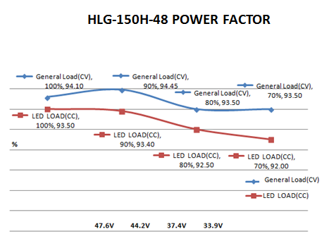
NOTE 2.4 Effect of output load on power factor (PF)
The effect of different types of load on power factor (PF) and the harmonic current is as shown in the chart below. The power factor of MEAN WELL’s LED power supply operating at LED load will be lower than at general load, and the total Vf level of LED in series will also affect power factor. Therefore, it is a better design to set the total Vf in LED luminaries close to the rated output voltage of the power supply.
There is a definition of SELV in IEC61347. Is it the same with IEC60950?
No, they are different. SELV means the LED driver will use a safety isolating transformer with double or reinforced insulation and the output voltage shall not exceed 120Vdc.
This is good for the end product safety certified if the LED driver with SELV output.
What is Type HL?
The requirement of Type HL is from UL8750. It provide one option for evaluation of LED drivers that are intended for use in a Class I, Division 2 hazardous location luminaires.
It is simplify the procedure for the manufacture to apply the explosion-proof luminaires.
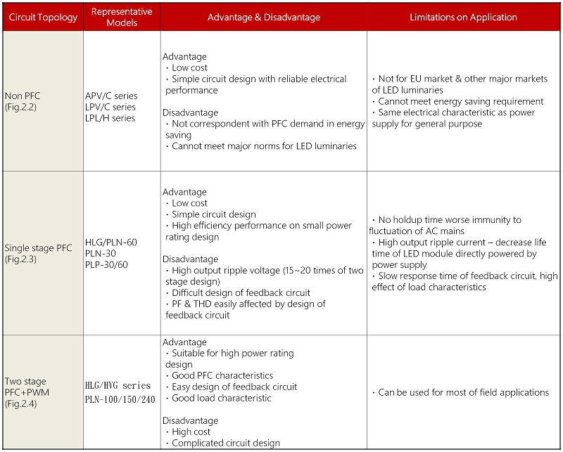
NOTE 2.5 Comparison of circuit topologies with power factor correction (PFC) function in LED power supply
MEAN WELL’s LED power supplies equipping with power factor correction function mainly adopt the two kinds of circuit topologies below. A Comparison between circuit topologies with and without PFC function is shown as the table below.
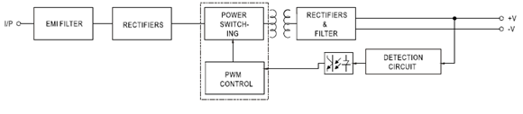
Fig.2.2: Block diagram of non-PFC circuit topology
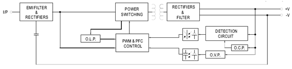
Fig.2.3: Block diagram of circuit topology with single stage PFC
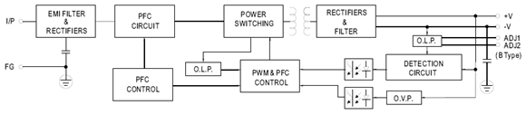
Fig.2.4: Block diagram of circuit topology with two-stage PFC
NOTE 2.6 Heat dissipation of LED
LED is actually not with high luminous efficiency. Only 30% of supplied power is converted into visible light; the remaining of 70% is lost as heat. Due to this, thermal design plays an extremely important role in LED applications. According to the temperature characteristics of LED, luminous flux will attenuate by 3% and reliability will decrease by 10% for every temperature increment of 5℃ on LED. Therefore, temperature rise of LED is the major factor in life time and light loss.
- All of MEAN WELL’s LED power supplies adopt thermal design of free air convection. Maximum operating temperature can reach 50℃~70℃. In addition, the metal enclosure of CLG series is able to release the heat through system case in where CLG series is installed, so as to improve system reliability.
- The life time of LED power supply is highly relevant to operating temperature. Take HLG-150 as example, for operations at the same load level, the lower the operating temperature, the longer its life time; for operations at the same operating temperature, the lighter the load, the longer its life time. When choosing a power supply, it is recommended to add a margin to the actual power usage to match the longer life time characteristic of LED. The relationship is as shown in Fig.2.5.
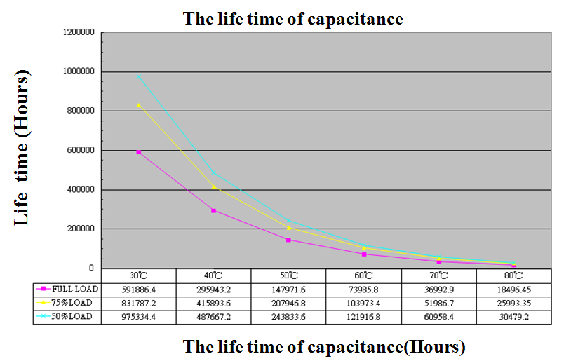
Fig.2.5: Relationship between output load, operating temperature and life time in LED power supply
- In Fig.2.6 (de-rating curve for HLG-150), in order to avoid high temperature rise and maintain the reliability of the power supply, the rated power capability needs to be de-rated when ambient temperature exceeds 60℃ for operation at 230Vac input. Due to the abovementioned, the management of operating temperature should be taken into consideration in system design.
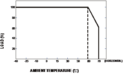
Fig. 2.6 De-rating curve for output load against ambient temperature in LED power supply
For a particular LED lighting design, each LED strip consists of 12 LEDs connected in series (VF=3.5V), 4 strips in parallel, and each strip requires 0.7A of drive current. Based on the above conditions, how do you select a suitable power supply?
First of all, the LED power supply must be able to work in constant current mode. LED forward voltage of each strip = 3.5V X 12pcs = 42V LED lamp total current requirement = 0.7A X 4 strips in parallel = 2.8A LED power requirement = 42V X 2.8A = 117.6W LED power supply’s rated voltage/power should be greater than what is required but should be as close to the actual requirement as possible. Use 48V/150W as the basic criteria to pick LED power supply then make sure actual voltage/power usage meets constant current region and PF>0.9 specifications (117.6W/150W = 78.4% > 75%). CLG-150A-48V with output current set at 2.8A can be used in this design.
Note: Each LED production lot will fall within a VF rank (e.g.3.4~3.6V). This LED tolerance must be taken into consideration during design.
How do you select suitable MW LED power supply?
- Select suitable wattage based on customer’s system requirements and application methods. Must also take excess power and driving method into consideration.
- For selection key points when using MW power supply to “directly” drive LED lamp refer to questions (A2) and (A3).
- For selection key points when using MW power supply in combination with LED driver IC to achieve high precision current control refer to questions (A2) and (A3).
- Based on LED power supply’s operating environment select suitable IP level and mechanical type (metal enclosure, plastic enclosure, and open frame PCB) for that environment.
- Is PFC function required or not? Single stage PFC is only suitable for LED load. Dual stage PFC is suitable for general applications.
- If LED system is based on direct drive, units with adjustable voltage and current should be considered for flexibility in changing voltage/current levels. Dimming function may also come in handy when LED brightness control is preferred.
- *Comparison Chart http://www.meanwell.com/product/images/led/LED_comparison_chart_en.pdf
*For those who chose to use single stage PFC products. Refer to Question D1for more instructions.
- *Comparison Chart http://www.meanwell.com/product/images/led/LED_comparison_chart_en.pdf
Same LED configuration as in question B1 with the exception of additional driver ICs. What is a suitable power supply unit to use?
First calculate for required voltage by combining total LED forward voltage and driver voltage drop of 2V. LED forward voltage of each strip = 3.5V x 12pcs = 42V Driver circuit required voltage = 42V + 2V = 44V LED total current requirement = 0.7A X 4 strips in parallel = 2.8A Driver circuit required wattage = 44V X 2.8A = 123.2W LED power supply's rated voltage/power should be greater than what is required but should be as close to the actual requirement as possible. Use 48V/150W as the basic criteria to pick LED power supply then make sure actual voltage/power usage meets constant current region and PF>0.9 specifications (123.2W /150W = 82.13% >75%) CLG-150A-48 with output voltage set at 44V can be used in this design
Why is that LED lamp designed with LED driver IC may sometimes cause power supply startup failure? (Output voltage gets clamped by LEDs and cannot rise to rated level)
Depending on circuit design, there could be different operational problems. See below:
- Boost mode driver IC:
The startup voltage of such driver IC is significant lower than the total LED forward voltage. For this reason, the IC will start up at very low voltage level usually about 1/2 of the power supply’s rated voltage and to meet rated power requirement, the startup current will reach 2 times the power supply’s rated current. When the power supply is unable to provide this current, the LED CC driver will not activate. - Buck mode driver IC:
If the selected power supply voltage is significantly higher than the LED forward voltage. For example, power supply provides 48V and the LED lamp only needs 24V and the power ratings are equivalent. When power supply voltage reached the LED conduction voltage, the power supply will immediately go into constant current mode. At this moment, the required power to start up the LED + driver is larger than what the power supply can provide causing malfunction of the driver circuit and the power supply to be clamped at LED forward voltage. For boost mode design, we recommend raising the startup voltage of the driver IC to be as close to the power supply voltage as possible or incorporate soft start function (see fig. 3). Wait until the power supply voltage is established before starting the driver. When selecting power supply for buck mode, the output voltage of the power supply should be as close to the LED total voltage as possible with excess power available (LED power/0.85).
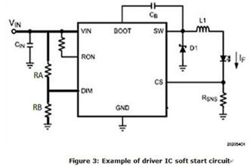
DIM PIN is the startup pin for most PWM based driver. It can also be designated as EN (Enable). DIM (or Enable) is at 0V the internal connection to SW pin will be open. When the DIM voltage reaches 1.5V (Typ), the IC will Turn ON. To set the Vstart for the DRIVER IC: Vstart = (VDIM/RB) x (RA+RB). The general rule is to set the Vstart at 5~10% higher than the total LED forward voltage.
What are the most common LED driving methods? What are its advantages and disadvantages?
What to consider when selecting LED power supply?
- Lighting system designed to work in direct drive mode
- The combined LED forward voltage range (upper and lower) must fall within LED power supply’s constant current voltage range. For example, the LED Vf spec is 3.4~3.6V, when 6 are connected in series the combined Vf will be 20.4~21.6V. In this case, a 24V unit must be selected with constant current region of 18~24V.Ø
- For models with active PFC and system PF requirement is >0.9, load usage must be higher than as specified in the PFC spec. Relationship between PF and output load can be found in figure 1. The typical requirement is 75% load or above. Double check the spec for the model you are using to confirm actual requirement.
- In areas with unstable AC voltage such as heavy industrial zone or generator supply utility, please select general usage LED series from table 1.
- Lighting system designed to work with driver IC
- The start up voltage of driver IC should be as close to the power supply rated voltage as possible.
- Driver IC needs stable voltage to function properly. So, it is highly recommended to use general usage series from table 1.
- For models with active PFC and system PF requirement is >0.9, load usage must be higher than as specified in the PFC spec. Relationship between PF and output load can be found in figure 1. The typical requirement is 75% load or above.
- Double check the spec for the model you are using to confirm actual requirement. When using driver IC, possible system EMI issue could arise. After completing lighting system design, EMI must be double checked. For suggestion on system EMI problem solving, refer to question 11.

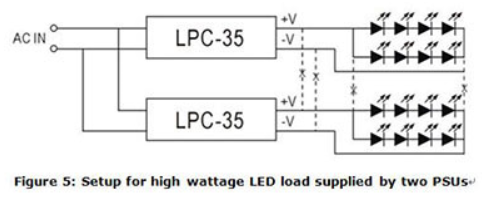
Can LED power supplies be connected in parallel?
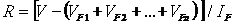
MW LED power supply does not have parallel “current sharing” function so it is not suitable for parallel connection. For high power requirement, please select higher wattage power supply or divide LED load into smaller subsections to be powered by individual power supplies. Example of such LED configuration can be found in figure 5. As shown in fig. 5, the connection between -V of the LPC-35 units should be severed and not connected in common. On the contrary, small wattage LED loads can be connected in parallel and be powered by a single high wattage power supply. But, the ability to divide current evenly must be taken into consideration.
What surge level can MW LED power supply withstand?
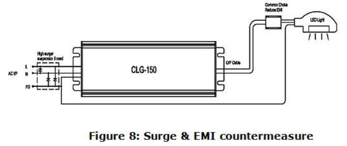
Among MW LED power supplies, CEN/ CLG and HBG, HLG, HLN, HLP, HVG, HSG have the highest surge capability. It can withstand heavy industry level of 4kV. If higher level is required, external ZNR (470V) or gas tube (500V) can be added as shown in figure 8. But, overall safety compliance must be taken into consideration. For application with numerous lamp sets, a SPD (Surge Protection Device) can be installed to meet surge regulation requirements.
What are CV, CC, and CV+CC which are often mentioned in LED power supply specification?
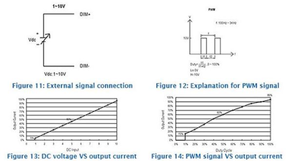
How to use ELN-30/60-XXD(P) Dimming function in applications?
As shown in fig 11&12, an external signal can be applied to “DIM+” and “DIM-.” The signal can be either DC voltage (D Type) or PWM (P Type). By changing the signal levels as shown below, the output current limit can be controlled by the user. Please note, the relationship between external signal and output current level is non-linear. It cannot be used for high precision dimming control.
Can MW recommend the dimmers compatible to the 3 in 1 dimming circuit?
3 in 1 dimming is the most commonly applications used in LED dimming with the feature that it does not have to work with any specific dimmer. The only thing that has to be verified is that whether the dimmer (1~10V/10V PWM/resistance) is compatible with the definition advised in our specs.
Which model should we select when attempting to dim a LED strip?
Generally speaking, LED strips would be connected with resistors in series, so the LED must be driven in CV mode. We will suggest those models offering CV dimming to be adopted, such as PWM series.
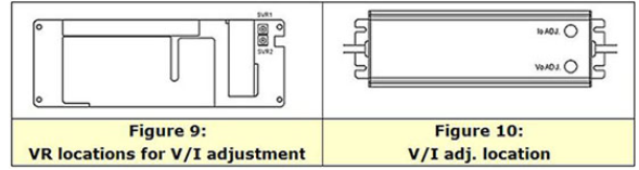
Does MW LED power supply allow adjustment of output voltage and current levels?
LED power supply comparison table to see which MW LED power supply allows for V/I adjustments. A suitable unit can be picked based on the type of adjustment required. For the allowed adjustment range, please refer to the spec sheet. Tuning of the voltage and current levels can be done through the built-in VRs/potentiometers. PLN/ELN requires removal of the top cover in order to access the internal SVR1 and SVR2, see figure 9 for VR locations. For other series, the VRs can be accessed through IoADJ and VoADJ holes after rubber stopper removal. After adjustments have been made, please make sure rate power is not exceeded and the rubber stoppers are properly reassembled.
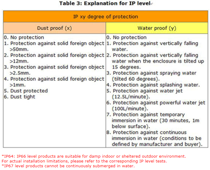
What does the IP level found on MW LED power supply mean (i.e. CLG-100 = IP67)?
MW LED power has dust/water proof design, primarily based on international standard IEC60529. Description of IP levels can be found in the table below:
How can we learn how many units of the model with 3 in 1 dimming can be controlled by one dimming device?
3 in 1 dimming circuit would drain 0.1mA per model. Dividing the rated current of the dimmer by the 0.1mA, and we could know how many units can be controlled by one dimming device. For resistance dimming applications, resistance for 100% dimming output would be 100K ohm divided number of models.
Can we use LED CC model as a charger?
MW has several charger products, and we suggest choosing them first. Chargers would be more suitable since they are designed for charging applications. Safety & Approvals should be taken into account. If you really cannot find a proper model in our chargers series, our LED CC models can be used as charger. Please choose suitable products after confirming the current and voltage specification on the datasheet of the battery.
To design a LED street lamp, what solution can MEAN WELL offer?
What is the main difference between 1~10V dimming and 0~10V dimming regarding applications?
With 1~10V dimming, the lighting unit can be dimmed down to 10%; with 0~10V dimming, it can be dim down to 0%, or say, dim to “off”.
There are so many MW dimming products. How can I make a choice? What are the pros and cons?
First, you have to know your Led lamp specification in order to screen out a suitable Led driver range (Wattage, Voltage, Max Current CC or CV). From those ranges, further check a compatible dimming function. Hereunder is a table to show you the pros and cons of Dimming Function you can find in MW's catalogue. 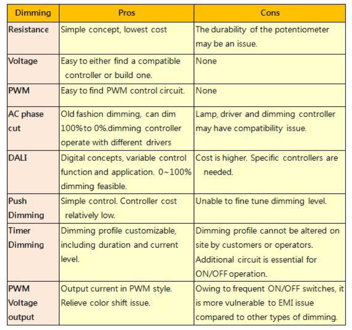
Can I use MW LED drivers at full load continuously? Most of the AC/DC power supply are suggested to use at 70% load.
LED Drivers are recommended operate at full load as long as it observes the working temperature specified in the datasheet, which means Tc measurement results should be equal to or less than the stated Tc in the datasheet. 5 years warranty complies as long as drivers operate within working Temp and Tc. Limit as well.
What is the current accuracy of LED SPS?
For LED SPS output current accuracy, please refer to product specification. For CC model, “CURRENT ACCURACY” is listed in SPECIFICATION section. For CC+CV model, please reference the OVER CURRENT range in PROTECTION of the SPECIFICATION section.
What is the difference between Single Stage and Two Stage Power Supply?
There are 2 types of Power Factor Correction circuits; one is Single Stage and the other is Two Stage. Single stage power supply combines functions of power factor correction and converter in one circuit but two stage use two separate circuits. Compared to Single Stage, Two Stage design is more complex and costly but the immunity performance of Two Stage PSU against AC mains is much better than that of Single Stage PSU; in addition, Two Stage manifests better ripple noises performance on output. Owing to that Single Stage is only suitable for fields with quality AC mains but Two Stage can be used in serious circumstance for LED drivers or as industrial switching power supplies.
Can I wire LDD or LDH in parallel or series?
LDD/LDH series comprises switching components; series or parallel connection will damage these switching components.
How long can I extend DC cable of the driver?
Owing to line (voltage)-drop, we suggest the extension made from AC cable. In case DC cable extension is necessary, please consider Line-Drop leading to insufficient Vf so that the LED model or lamp may fail to switch ON. Moreover, EMC performance and characteristic may also be affected by DC cable extension.
How am I supposed to read the LED V-I dotted line & tolerance definition in the specification?
Mean Well’s LED product specification normally exhibits V-I characteristics. Per the characteristics, there are generally two types of drivers, “CC” type and “CC+CV” type. “CC” type of driver is suitable only for LED applications whereas “CC+CV” for either LED applications or general switching power supply applications. The section that is not suitable for LED applications are represented by dotted line, and based on the protection procedures it can be categorized into hiccup mode and constant current mode; in this section, the tolerance of current is not defined but only the characteristic of current is displayed. If customers attempt not to see a very high current under short circuit condition, those models with hiccup mode for this section can be selected; if there are applications with motors or capacitive load, those with constant current can be chosen.
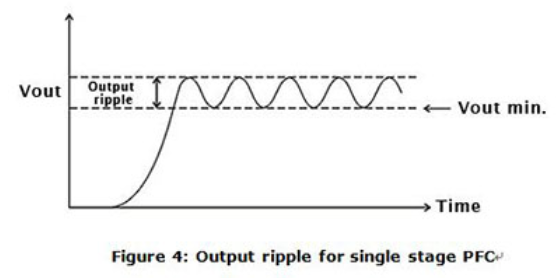
Why is that during LED power supply operation the LED sometimes varies in brightness or flickers?
MW developed many power supplies series specifically for LED application. Single stage PFC was used in such developments due to low cost. This topology has the following restrictions:
- AC fluctuation
This topology does not use input bulk capacitor. For this reason, in areas with low AC quality, output voltage and current may become unstable causing variation in LED brightness. If the input AC voltage is stable then this problem will not occur. - Output ripple
This is also caused by lack of input bulk capacitor. As compared to power supplies using dual stage PFC, the ripple will be significantly larger (see Figure 4). There could be instances where the low end of the ripple may be too low for the driver IC to operate properly and the LEDs will start to flicker. To solve this type of problem, the output voltage can be adjusted higher so the low end is higher than the driver’s minimum working voltage. Or simply select a PSU with higher rated voltage. - Current harmouics
Single stage PFC power supplies are optimize for constant current drive. Using these supplies as constant voltage sources (such as application including cascading a constant current driver IC), the harmonics might be worsen in this case. When operating in areas with unstable utility voltage or with driver IC, we highly recommend using general application types as found in table 1. Avoid using single stage PFC if possible, or contact MEANWELL.
I cannot do dimming with MW LED drivers?? Why?
First, please make sure your LED lamp or modules are Constant Current (CC) driven or Constant Voltage (CV) driven. If you are using CC-driven LED applications, please verify that MW LED driver’s rated current on datasheet can match your LED current requirement. If you are using CV LED applications, we offer PWM series for CV dimming applications.
How to find products you need in MEAN WELL website?
Click “Products” on the website Menu. Four methods are provided to search MEAN WELL power supply products.
1. Series Search
Click “product style” such as DIN Rail, LED Driver or Charger, and you can rapidly find the corresponding
product series. Through wattage and function information, you will find the products you need.
2. Quick Search
By choosing product type and electrical characteristic, related power supply and specification are shown
below.
3. Product Search
It's classified by the application type, such as Parallel Series, Medical Type, and DC/AC Inverter. Choose
the function or characteristic, and you can find the related products and specifications.
4. Direct Search
If you know the series name, click “magnifier” icon from the upper right of MEAN WELL website, and type
the complete or part name to search the related product information.
What product information does MEAN WELL website provide?
The product information shown on MEAN WELL website is as below.
1. Specification
Details of product features, electrical specification, function, and mechanical specification can be found in the specification page.
2. Test report
The report content includes design verify test, safety & EMC test, and reliability test, ensuring the user safe through inspection,
3. Certificate
The certificate from accredited certification body is provided for customers' reference.
4. User manual
User manual provides detailed product instruction and considerations.
If the suitable product cannot be found, how to contact MEAN WELL?
You can send your product demand to local distributors at first, and the distributors can provide immediate service and suggestion. Besides, you can find “Contact Us” on website to fill out Sales Inquiry Form and we will reply your query promptly.
How to know the product discontinued information?
Providing the best price-performance ratio of standard power supplies and services are MEAN WELL enterprise mission. To comply with the latest updated international safety regulations, MEAN WELL develops the corresponding new high cost-performance products. Through “Products”, you can see “Not Recommended for New Design” and “Discontinued Products”. The former one shows models which will be gradually discontinued and replaced in the future. The latter one is models that are going to be discontinued and EOL.
What is the purchasing channel for MEAN WELL products?
For small and medium quantity demands, local distributors offer better price and enough stock for your timely delivery. However, for further contact to MEAN WELL, please fill out “Sales Inquire Form” in the “Contact Us” page, service will be offered promptly.
How to know MEAN WELL distributors information?
MEAN WELL has authorized distributors all over the world. You can find “Distributors” to search local distributors by area and product type. Our distributors will surely provide high quality service.
How to learn MEAN WELL new product launching announcement?
MEAN WELL develops new products constantly. Click “New Products” in “News” page for acquiring complete model information and key features.
Where to find the product test report?
To discover product complete test reports, click product information link and the report shows various information, such as electrical characteristic, protection, control function, stability, safety, and EMC.