
Notes on LED Drivers & Luminaires
NOTE 1.1
Explanation of LED fundamentals
LED is a light emitting semiconductor device with diode-like characteristics. As forward current flows through the P-N junction of the semiconductor material, photons are released as a result of electrons moving across the diode and falling into the empty holes in the P-type layer. Depending on the photon’s frequency, it could either be invisible to the human eye (infrared portion) or be part of the visible spectrum. The lasted development in LED technology involves coating blue LED with phosphor to create white LED.
The V-I curve of LEDs is similar to diodes. Please refer to figure 1.1
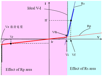
Figure 1.1: LED V versus I characteristic
White LEDs are generally used for lighting applications, the brightness of such device increases proportionally with the increase in forward conduction current. Due to the rise in demand for high power, high luminance white LED in the lighting industry, specifications are being standardized. Forward voltage is typically within the range of 3.0~3.5V with forward current of 350/700/1050mA resulting in power rating of 1/2/3W.
NOTE 1.2
LED applications
Advantages of LEDs include low heat dissipation, diverse applications, miniaturization, high tolerance to shock/vibration, and ability to focus light beam. The use of white LED in the lighting industry is accelerated by the continuing improvement in luminous flux and efficiency. Typical applications include building architecture (wall lighting, wall decoration, garden lighting, spot lighting, stairway lighting, and patio lighting), outdoor use (street light, park light, and lamp post), commercial use (office lighting, sign board, display cabinet lighting), and home use (cabinet lighting, room lamination, desk lamp, and etc).
NOTE 1.3
LED lifetime and reliability
Since LED is part of the solid-state semiconductor device family, when properly designed-in, it has excellent lifetime and reliability figures. The lifetime of LED is typically between the range of 50,000~100,000 hrs. This exceeds the lifetime of the traditional lighting device (1,000~10,000 hrs) by a large margin. Extra attention must be given to cooling of LED and design of LED driver or else you risk premature failure and accelerated the decrease in luminance (refer to figure 1.2). The key to achieving energy conservation, high efficiency, and long lifetime is to select a suitable power source/drive method and provide proper cooling for the LEDs.
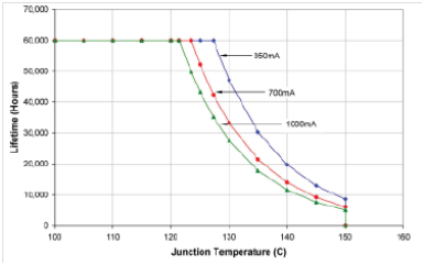
Figure 1.2: LED junction temperature versus lifetime
NOTE 1.4
LED drive methods
The main factor to driving a LED is the introduction of forward current. However, due to its nonlinear V-I characteristic, high Vf manufacturing tolerance, and Vf sensitivity to temperature change, the most common types of voltage source used are limited to either constant voltage or constant current. The drawback of using constant voltage source is that LEDs will not produce the same brightness, resulting in uneven reliability, decrease in luminance and lifetime. For these reasons, the constant current voltage source is more preferable when it comes to driving high power LEDs. Just as named, the constant current source is not susceptible to the variations in forward voltage. Its current will remain at a constant level regardless of the shift in LED Vf. Thus, constant brightness can be easily achieved. Constant current can also be attained by using a driver circuit with current sense resistive network so no adjustment of the power supply voltage is required.
NOTE 1.5
Introduction to Constant Voltage (C.V.) Mode and Constant Current (C.C.) Mode of LED Power Supply
Most of the traditional switching power supplies provide a constant voltage (C.V.) to the load. For example, MEAN WELL’s single output model RS-25-5 can provide 5V/0~5A to power all kinds of load. Its output voltage maintains at the constant value of 5V while its output current varies from 0~5A based on the load condition. When the loading is over 5A which is its rated current, the power supply unit will go into “overload protection” mode (generally speaking the activated range of overload protection is 105%~150% of rated output power). There are many different protection types that are often seen in the design of MEAN WELL power supply such as shutdown type (PSU will be shut off output), hiccup type (output voltage/current will be pulsing), and constant current type (output current will be fixed at a constant value between 105~150% of rated output current and the output voltage will go down to a low level). The power supply is under abnormal condition when the overload protection has been activated, so it is not suitable to let the power supply unit operate under this situation continuously. Equipped with “hiccup type” as their overload protection mode, the LPV, LPH-18 and LPL-18 series in MEAN WELL LED power supply family are considered to be “constant voltage power supply”. For LED related applications, it can be used in system incorporated with LED constant current driver IC (Fig. 1.5) or series connected with a ballast resistor (Fig. 1.4).

The so-called constant current (C.C.) LED power supply basically refers to the “constant current protection” concept and its output current is maintained at a fixed value by means of feedback control (this fixed current level will be close to its rated output current). The only difference is : Under constant current (C.C.) operation mode (or constant current protection mode), the C.C. LED power supply is still within the normal operating range and all the components have been chosen to continuously provide this constant current output. Generally speaking, the power supply unit will operate under constant current region only when the system design belongs to “LEDs drive by the power supply directly” (Fig. 1.3).

Figure 1.6: Typical LED power supply I-V curve
Fig. 1.6 is the I-V characteristic curve of a typical constant current LED power supply. The “constant current region” for each series of C.C. LED power supply may be different because of the different circuit design. As the figure shown above, the PSU will operate in the constant current region only when the output voltage is kept at 50% of rated output voltage or higher, so the sum of VF of all series connected LEDs should be higher than this limitation. If the sum of VF of all series connected LEDs can’t achieve 50% of rated output voltage, the power supply will go into the “hiccup region” and cannot drive the LEDs properly. Currently most of MEAN WELL’s LED power supplies can provide constant current output and the suitable operation region for directly connected LEDs is also specified in their SPECs (in the column of “Constant current range”). The constant current region can be 3V~100%VO, 9V~100%VO, or 70%~100%VO in different product series because of the difference of circuit design (concerning Harmonic Class C compliance, the lower limit may reach 75% of rated output voltage for some models with PFC function). When using power supply to drive LEDs directly, designer of lighting fixture should make sure that the VF sum of LEDs connected in series is high enough to operate the C.C. LED PSU in the correct region.
In fact, MEAN WELL’s constant current LED power supplies also possess the feature of “C.V. + C.C.”. That means before reaching the “constant current region”, they can be operated within the “constant voltage region” just like traditional power supplies. In this region, system design must incorporate suitable “LED drive IC” or “series connected with a ballast resistor”; after entering the “constant current region”, the PSU can provide constant current as the output and hence can drive the LEDs directly. We can find that the “C.V. + C.C.” characteristic can be used in many different LED installations and make the system design more flexible.
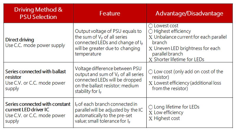
Below is the comparison chart of three different LED driving alternatives:
NOTE 1.6
LED lamp driver structure
The most often seen LED lamp setup is the series configuration because this ensures equal brightness to each of the LEDs. Even if the lamp consists of the same LED components from the same production lot there will still be slight differences in the forward voltage. As the working temperature increases, the LED forward voltage is bound to decrease leading to an increase in the forward current. This is why it will be necessary to add the current limiting circuit to the LED setup. The most common driving structures are as below:
- LED directly driven by a power supply Figure 1.7 This setup is the most cost-effective and wirings are simple. The designer will only have to worry about LED characteristics. Once that is taken care off, all the designer has to do is select a stable power supply with constant current limiting. However, there could still be issues with equal current sharing between each of the LED strings. Matrix LED structure can be used to minimize extensive damage from the
- Series connection of LED current limiting resistor, refer to Figure 1.8 Series The advantage of this architecture is that it is inexpensive and rather easy to assemble. Better balance in output current as compared to the direct drive method. The disadvantages are high power dissipation of these resistors, If current varies with the change in voltage, LED brightness may be uneven, cannot control current precisely and lack of protection for the LEDs.
- Power supply in combination with linear driver IC, see figure 1.9 The cost of this structure is moderate. Other advantages include long lifetime for both LED and the power supply, simplicity of circuit design. Disadvantages includes higher cost as compared to using driver resistor with just as much power dissipation, and unsuitable for use with high tolerance voltage source.
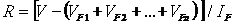
- Power supply in combination with PWM constant current driver IC, see figure 1.10 This structure is the mainstream driving method preferred by most LED lighting manufacturer. The main reasons are steadiness of current control and even current sharing. Other advantages include long lifetime for both the LED and the power supply. Disadvantages include higher cost as compared to other driving methods, complicity in connection, the PWM driver can cause EMC interference and produce high frequency audio noise.
failure of just a few LED. If a MEAN WELL constant current LED power supply is used to drive LEDs, the direct connection is possible and current limiting resistors and LED driver ICs are not required to somewhat balance the current flow to each LED string. However, the LED must be ranked in order to minimize large differences in Figure 1.7 combined VF of each of the LED strings which can lead to unbalance current flow to some of the strings and cause part of the LED structure to be damaged from the high current flow.
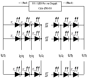
Figure 1.7 Constant current power supply drive LED load directly
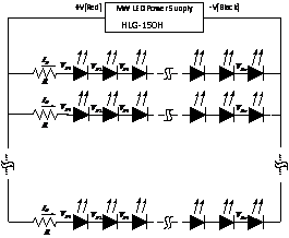
Figure 1.8: Constant current or constant voltage power supply with LED driver resistor
Example:
The use of CLG-150-30(30V/5A) to drive 8 LEDs in series and 8 strings in parallel
V : LED power supply rated output voltage
VF: LED forward voltage (around 3.5V)
IF: : LED forward current (about 625mA)

Linear constant current driver can not automatically adjust the current flow to the LED. It does not balance current as well as PWM constant current driver. Its basic IC structure composes of resistor + electronic switch. LED drive current is regulated through the control of the switch’s conduction level.
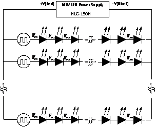
Figure 1.9: Constant current or constant voltage power supply with linear LED driver
The PWM constant current driver will automatically adjust current flow to achieve balance in current for each LED string thus insure each branch has equal brightness. Main topologies include buck, boost, and buck-boost. Either pulse width or frequency is modulated to maintain constant current.

Figure 1.10: Constant current or constant voltage power supply with PWM constant current LED driver
NOTE 2.1
Instructions on Assembly
- As step 1 shown in figure 2.1, connect LED luminaries to the output cable of Mean Well LED power supply.
- As step 2 shown in figure 2.1, connect the input cable of Mean Well LED power supply to AC mains. ! CAUTIONS: Step 1 should always come before step 2. If step 2 comes first, a high transient surge current will go into the LED luminaries and it can damage LEDs in an LED luminaries without LED driver IC.
Fig.2.1: Assembly of LED power supply
NOTE 2.2
Protection function
All of MEAN WELL’s LED power supplies are designed with protection functions against inrush input current, peak input voltage, short-circuit at output, overload (OLP) at output and over voltage (OVP) at output. Some models also equipped with over temperature protection (OTP). Please refer to Mean Well’s switching power supply technical manual for detailed information.
NOTE 2.3
Effect of output load on efficiency
The types and levels of output load have significant effects on the efficiency of a power supply when operating at normal conditions. The chart below presents the change of the efficiency of HLG-150-36 operating at 70~100% LED load and 70~100% general load, and indicates that the efficiency will be lower as the total Vf (forward voltage) of LEDs in series is lower when LEDs are directly powered by LED power supply. Therefore, it is a better design to set the total Vf of LEDs in series at 85~95% of the rated voltage of the power supply.
NOTE 2.4
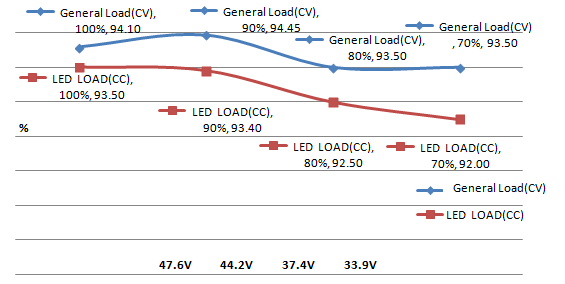
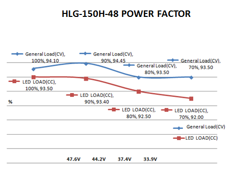
Effect of output load on power factor (PF)
The effect of different types of load on power factor (PF) and the harmonic current is as shown in the chart below. The power factor of MEAN WELL’s LED power supply operating at LED load will be lower than at general load, and the total Vf level of LED in series will also affect power factor. Therefore, it is a better design to set the total Vf in LED luminaries close to the rated output voltage of the power supply.
NOTE 2.5
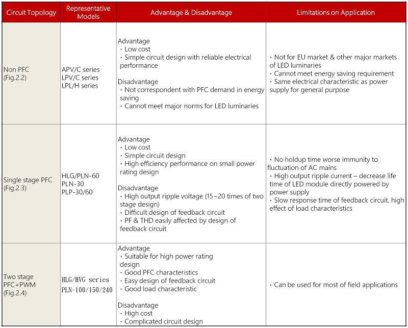
Comparison of circuit topologies with power factor correction (PFC) function in LED power supply
MEAN WELL’s LED power supplies equipping with power factor correction function mainly adopt the two kinds of circuit topologies below. A Comparison between circuit topologies with and without PFC function is shown as the table below.
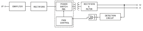
Fig.2.2: Block diagram of non-PFC circuit topology
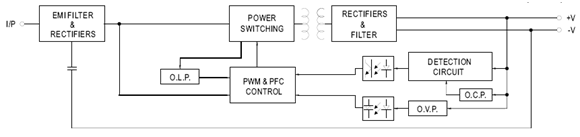
Fig.2.3: Block diagram of circuit topology with single stage PFC
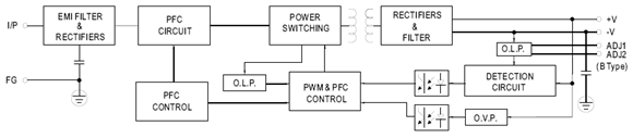
Fig.2.4: Block diagram of circuit topology with two-stage PFC
NOTE 2.6
Heat dissipation of LED
LED is actually not with high luminous efficiency. Only 30% of supplied power is converted into visible light; the remaining of 70% is lost as heat. Due to this, thermal design plays an extremely important role in LED applications. According to the temperature characteristics of LED, luminous flux will attenuate by 3% and reliability will decrease by 10% for every temperature increment of 5℃ on LED. Therefore, temperature rise of LED is the major factor in life time and light loss.
- All of MEAN WELL’s LED power supplies adopt thermal design of free air convection. Maximum operating temperature can reach 50℃~70℃. In addition, the metal enclosure of CLG series is able to release the heat through system case in where CLG series is installed, so as to improve system reliability.
- The life time of LED power supply is highly relevant to operating temperature. Take HLG-150 as example, for operations at the same load level, the lower the operating temperature, the longer its life time; for operations at the same operating temperature, the lighter the load, the longer its life time. When choosing a power supply, it is recommended to add a margin to the actual power usage to match the longer life time characteristic of LED. The relationship is as shown in Fig.2.5.
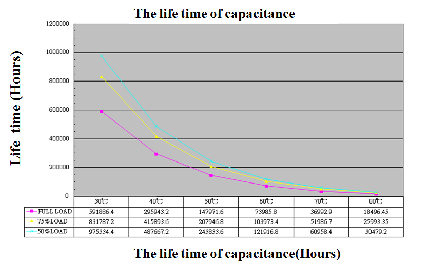
Fig.2.5: Relationship between output load, operating temperature and life time in LED power supply
- In Fig.2.6 (de-rating curve for HLG-150), in order to avoid high temperature rise and maintain the reliability of the power supply, the rated power capability needs to be de-rated when ambient temperature exceeds 60℃ for operation at 230Vac input. Due to the abovementioned, the management of operating temperature should be taken into consideration in system design.
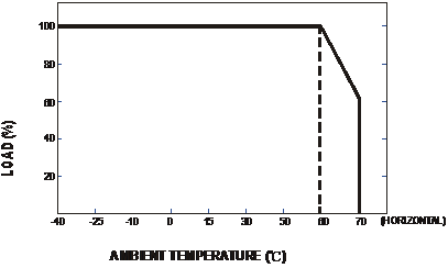
Fig. De-rating curve for output load against ambient temperature in LED power supply
NOTE 2.7
Adjustment of output voltage and current
Some MEAN WELL’s LED power supplies equip with functions of adjustable output voltage and current. Models with IP67 design (potted with heat transfer silicone) do not allow adjustment of output voltage and current, but HLG-150A/240A is with special design that allows external adjustment; for models with plastic enclosure, adjustment can only be made after taking apart the top cover. Adjustable voltage range will be +/-10% or +0/-15% of rated value and adjustable current range will be about 50~100% of rated value.
NOTE 2.9
Suggested solutions for EMC of LED luminaries
- Metal enclosure grounded to FG (Frame Ground)
- Wiring
- High surge level requirement
- LED module with driver IC
For applications with FG connection, it is suggested to bond the metal cases of LED power supply and LED module to FG to reduce EMI (Electromagnetic Interference) of the whole system.
Since the input and output cable length can be meters due to actual field applications, the common mode noise can be highly significant. To effectively reduce the noise, a clip-on common-mode core can be installed on the wiring close to LED module. This solution also applies if AC input cable is too long. Please refer to Fig.2.9 for illustration.
In order to meet requirement of surge level for outdoor applications, the surge immunity of HLG-60/100/150/240 is designed to be up to 4KV. For surge immunity of higher level, varistors or gas tubes (500V rating) can be installed in the outside of the power supply. But the configuration should also comply with requirements in safety norms. Please refer to Fig.2.9 for illustration.
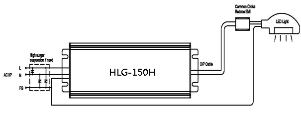
Fig.2.9: Illustration of suggested solutions for EMI and surge immunity
Since LED driver IC is a circuit topology employing high frequency switching (hundreds of KHz to several MHz), using it to deliver constant current to LED modules can complicate EMI debugging. Due to the EMI concerns, it is more than important to suppress the noise from driver IC. The PCB layout should focus on the size of driver IC’s ground trace and configuration of In/out capacitors and inductors. It is suggested that common choke, differential choke and high-frequency X capacitor should be incorporated into the PCB layout between the output side of power supply and the circuit of LED driver IC. Please refer to Fig.2.10 for illustration.
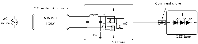
Fig.2.10 Illustration of suggested EMI solutions for LED driver IC