MEAN WELL’s power supplies have been used in a wide variety of electronic equipments, including factory control, IT, communication, appliances, medical, lighting, billboards, security, vehicle, etc…. , which is capable of meeting your needs.
응용 분야
For a particular LED lighting design, each LED strip consists of 12 LEDs connected in series (VF=3.5V), 4 strips in parallel, and each strip requires 0.7A of drive current. Based on the above conditions, how do you select a suitable power supply?
First of all, the LED power supply must be able to work in constant current mode. LED forward voltage of each strip = 3.5V X 12pcs = 42V LED lamp total current requirement = 0.7A X 4 strips in parallel = 2.8A LED power requirement = 42V X 2.8A = 117.6W LED power supply’s rated voltage/power should be greater than what is required but should be as close to the actual requirement as possible. Use 48V/150W as the basic criteria to pick LED power supply then make sure actual voltage/power usage meets constant current region and PF>0.9 specifications (117.6W/150W = 78.4% > 75%). CLG-150A-48V with output current set at 2.8A can be used in this design.
Note: Each LED production lot will fall within a VF rank (e.g.3.4~3.6V). This LED tolerance must be taken into consideration during design.
Same LED configuration as in question B1 with the exception of additional driver ICs. What is a suitable power supply unit to use?
First calculate for required voltage by combining total LED forward voltage and driver voltage drop of 2V. LED forward voltage of each strip = 3.5V x 12pcs = 42V Driver circuit required voltage = 42V + 2V = 44V LED total current requirement = 0.7A X 4 strips in parallel = 2.8A Driver circuit required wattage = 44V X 2.8A = 123.2W LED power supply's rated voltage/power should be greater than what is required but should be as close to the actual requirement as possible. Use 48V/150W as the basic criteria to pick LED power supply then make sure actual voltage/power usage meets constant current region and PF>0.9 specifications (123.2W /150W = 82.13% >75%) CLG-150A-48 with output voltage set at 44V can be used in this design
Why is that LED lamp designed with LED driver IC may sometimes cause power supply startup failure? (Output voltage gets clamped by LEDs and cannot rise to rated level)
Depending on circuit design, there could be different operational problems. See below:
- Boost mode driver IC:
The startup voltage of such driver IC is significant lower than the total LED forward voltage. For this reason, the IC will start up at very low voltage level usually about 1/2 of the power supply’s rated voltage and to meet rated power requirement, the startup current will reach 2 times the power supply’s rated current. When the power supply is unable to provide this current, the LED CC driver will not activate. - Buck mode driver IC:
If the selected power supply voltage is significantly higher than the LED forward voltage. For example, power supply provides 48V and the LED lamp only needs 24V and the power ratings are equivalent. When power supply voltage reached the LED conduction voltage, the power supply will immediately go into constant current mode. At this moment, the required power to start up the LED + driver is larger than what the power supply can provide causing malfunction of the driver circuit and the power supply to be clamped at LED forward voltage. For boost mode design, we recommend raising the startup voltage of the driver IC to be as close to the power supply voltage as possible or incorporate soft start function (see fig. 3). Wait until the power supply voltage is established before starting the driver. When selecting power supply for buck mode, the output voltage of the power supply should be as close to the LED total voltage as possible with excess power available (LED power/0.85).
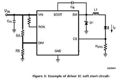
DIM PIN is the startup pin for most PWM based driver. It can also be designated as EN (Enable). DIM (or Enable) is at 0V the internal connection to SW pin will be open. When the DIM voltage reaches 1.5V (Typ), the IC will Turn ON. To set the Vstart for the DRIVER IC: Vstart = (VDIM/RB) x (RA+RB). The general rule is to set the Vstart at 5~10% higher than the total LED forward voltage.
Can LED power supplies be connected in parallel?
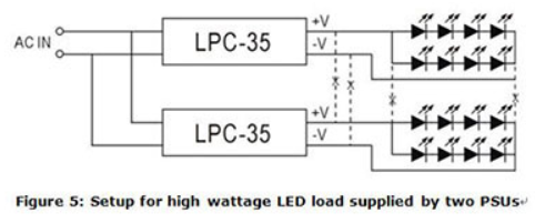
MW LED power supply does not have parallel “current sharing” function so it is not suitable for parallel connection. For high power requirement, please select higher wattage power supply or divide LED load into smaller subsections to be powered by individual power supplies. Example of such LED configuration can be found in figure 5. As shown in fig. 5, the connection between -V of the LPC-35 units should be severed and not connected in common. On the contrary, small wattage LED loads can be connected in parallel and be powered by a single high wattage power supply. But, the ability to divide current evenly must be taken into consideration.
What surge level can MW LED power supply withstand?
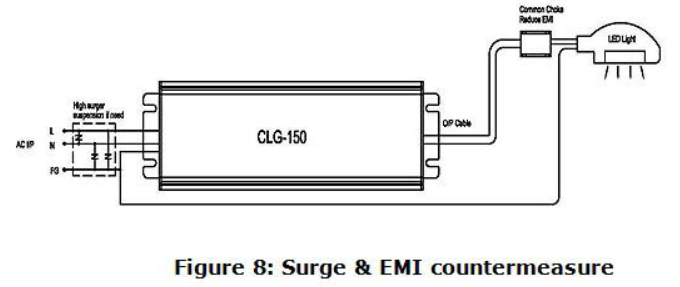
Among MW LED power supplies, CEN/ CLG and HBG, HLG, HLN, HLP, HVG, HSG have the highest surge capability. It can withstand heavy industry level of 4kV. If higher level is required, external ZNR (470V) or gas tube (500V) can be added as shown in figure 8. But, overall safety compliance must be taken into consideration. For application with numerous lamp sets, a SPD (Surge Protection Device) can be installed to meet surge regulation requirements.
Can MW recommend the dimmers compatible to the 3 in 1 dimming circuit?
3 in 1 dimming is the most commonly applications used in LED dimming with the feature that it does not have to work with any specific dimmer. The only thing that has to be verified is that whether the dimmer (1~10V/10V PWM/resistance) is compatible with the definition advised in our specs.
Which model should we select when attempting to dim a LED strip?
Generally speaking, LED strips would be connected with resistors in series, so the LED must be driven in CV mode. We will suggest those models offering CV dimming to be adopted, such as PWM series.
How can we learn how many units of the model with 3 in 1 dimming can be controlled by one dimming device?
3 in 1 dimming circuit would drain 0.1mA per model. Dividing the rated current of the dimmer by the 0.1mA, and we could know how many units can be controlled by one dimming device. For resistance dimming applications, resistance for 100% dimming output would be 100K ohm divided number of models.
Can we use LED CC model as a charger?
MW has several charger products, and we suggest choosing them first. Chargers would be more suitable since they are designed for charging applications. Safety & Approvals should be taken into account. If you really cannot find a proper model in our chargers series, our LED CC models can be used as charger. Please choose suitable products after confirming the current and voltage specification on the datasheet of the battery.
There are so many MW dimming products. How can I make a choice? What are the pros and cons?
First, you have to know your Led lamp specification in order to screen out a suitable Led driver range (Wattage, Voltage, Max Current CC or CV). From those ranges, further check a compatible dimming function. Hereunder is a table to show you the pros and cons of Dimming Function you can find in MW's catalogue. 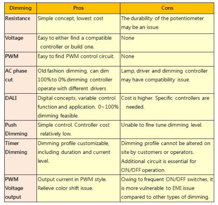
Can I use MW LED drivers at full load continuously? Most of the AC/DC power supply are suggested to use at 70% load.
LED Drivers are recommended operate at full load as long as it observes the working temperature specified in the datasheet, which means Tc measurement results should be equal to or less than the stated Tc in the datasheet. 5 years warranty complies as long as drivers operate within working Temp and Tc. Limit as well.
Can I wire LDD or LDH in parallel or series?
LDD/LDH series comprises switching components; series or parallel connection will damage these switching components.
How long can I extend DC cable of the driver?
Owing to line (voltage)-drop, we suggest the extension made from AC cable. In case DC cable extension is necessary, please consider Line-Drop leading to insufficient Vf so that the LED model or lamp may fail to switch ON. Moreover, EMC performance and characteristic may also be affected by DC cable extension.
Why is that during LED power supply operation the LED sometimes varies in brightness or flickers?
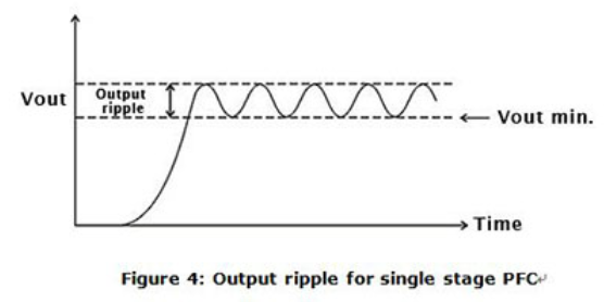
MW developed many power supplies series specifically for LED application. Single stage PFC was used in such developments due to low cost. This topology has the following restrictions:
- AC fluctuation
This topology does not use input bulk capacitor. For this reason, in areas with low AC quality, output voltage and current may become unstable causing variation in LED brightness. If the input AC voltage is stable then this problem will not occur. - Output ripple
This is also caused by lack of input bulk capacitor. As compared to power supplies using dual stage PFC, the ripple will be significantly larger (see Figure 4). There could be instances where the low end of the ripple may be too low for the driver IC to operate properly and the LEDs will start to flicker. To solve this type of problem, the output voltage can be adjusted higher so the low end is higher than the driver’s minimum working voltage. Or simply select a PSU with higher rated voltage. - Current harmouics
Single stage PFC power supplies are optimize for constant current drive. Using these supplies as constant voltage sources (such as application including cascading a constant current driver IC), the harmonics might be worsen in this case. When operating in areas with unstable utility voltage or with driver IC, we highly recommend using general application types as found in table 1. Avoid using single stage PFC if possible, or contact MEANWELL.
I cannot do dimming with MW LED drivers?? Why?
First, please make sure your LED lamp or modules are Constant Current (CC) driven or Constant Voltage (CV) driven. If you are using CC-driven LED applications, please verify that MW LED driver’s rated current on datasheet can match your LED current requirement. If you are using CV LED applications, we offer PWM series for CV dimming applications.
